|
|
|
Pseudo Celtic Cross: Description and Build Notes
A Simple Cross Similar in Style to a Celtic Cross
This is my take on a design that I saw on a YouTube video by “Sawdust and Splinters”. It is titled, “Make a BEAUTIFUL Wooden Cross in Just 30 Minutes”. I don’t know if that was just click-bait, but it took me significantly longer than 30 minutes to make.
I called it a Pseudo Celtic Cross because I think in a true Celtic cross, there would be one loop, woven under and over itself alternately. In this cross, the loops are woven "under" and "over" each other, but there are two loops rather than one.
The basic design is hers, although I made one significant change. I found the video a little short on some details, and hopefully this web page will cover those more clearly.
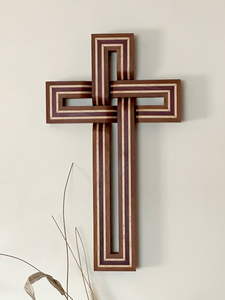
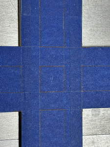
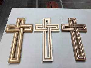
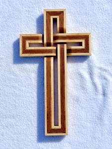
The finished product is this:
|
The major change that I made was that her crosses were made with a single type of wood. I thought it would be much better to use multiple colors of wood. I like the approach of having a “stripe” running along the strips because the stripe is interrupted where one piece “ducks under” the other piece. I think that makes for a much stronger illusion that one piece is passing behind the other.
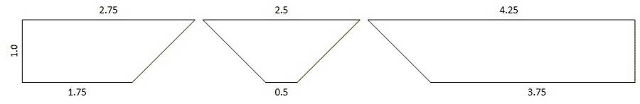
The cross basically consists of four U-shaped arms, where three of them are identical to each other, and the fourth is longer. All of the pieces are 1-inch wide. The gap in the “U” is 0.5 inches wide. This makes each of the 4 end pieces (with 2 miters each) 2.5 inches long along the long side. The sides of the “U” only have a miter cut on one end. The short arms have sides that are 2.75 and 4.25 inches long. The long arm has sides that are 6 inches longer than the short arms.
There are three key dimensions that need to be hit very accurately:
- The width of the strips need to be exactly 1 inch wide.
- The short side of the end pieces, which defines the gap, must be exactly 0.5 inches long.
- The difference in length between the two sides of each arm must be exactly 1.5 inches long.
Of course, these numbers can be adjusted as you see fit, but these are the numbers I got from the YouTube video and which I used. In particular, the difference in lengths between the two sides needs to be equal to the sum of the width of the strips and the gap.
The thickness of the strips is not critical. Mine were around 0.75 inches. If it gets much thinner than this, then I think you might have issues with the joint at the “duck under”.
I found it convenient to work with 24-inch long raw strips. I could get two short arms or one long arm out of each strip. That meant that I needed 3 24-inch strips per cross, and I had a half strip left over.
As I said earlier, I liked the idea of having a stripe down the middle of each strip, made with a contrasting species of wood. I experimented with using 2 types of wood and 3 types of wood.
The center stripe was 1/4 inch wide. If there were only 2 types of wood, this made the strip as 3/8, 1/4, 3/8. If I used 3 types of wood, the in-between strip was 1/8 inch wide. This made the strip as 1/4, 1/8, 1/4, 1/8, 1/4 in an ABCBA pattern.
The main types of wood I used were curly maple and mahogany, along with purpleheart and black walnut.
Note that the pictures below are taking from a number of different builds. I think I made a total of 7 by the end. So one picture may show one color of wood, and the “next” picture may show the next step from a different build, so the wood colors won’t match.
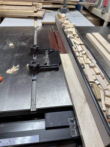
The first step was to cut a number of strips of wood from the different species, with the various widths I need for that build. I made the outside strips 1/8 inch thicker than necessary. For example, in the 2-type design, I wanted the finished thickness of the outside type to be 3/8, but when I cut the strips, I actually cut them 1/2 inch wide. This would be trimmed to the final thickness later.
There are many ways to cut thin strips of wood. My preferred method takes advantage of a DRO that I installed on my table saw fence. I know that my saw blade has a 1/8 inch kerf. I would make a skim cut so that the thickness of my raw board was exactly the distance from the blade to the fence. Then I would put the DRO in “incremental mode”, so that it read 0. Then I would adjust the fence until it read my desired thickness plus the 1/8 inch for the kerf. For example, to cut a 1/8 inch strip, I would move the fence until the DRO read 1/4. After that cut, I would reset the DRO to 0, and repeat the process.
|

|
When I was done with this, I had a large number of 24-inch long strips of various thickness.

|
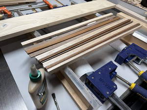
The next step was to glue them up into the 1.25 inch raw strips. This might have been easier if I had first run my raw boards through a planer to get them all the same thickness, but I didn’t do this. All of the different species were nominally about 3/4 inch thick, but some were thicker than others. This made the glue-up slightly more complicated.
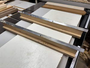
For the glue-up, I used a pair of rails that I had made years ago for gluing up panels. These were just some aluminum angle iron screwed into some wooden supports. I glued up three 24-inch boards at the same time, with a caul on each side to spread out the clamping force. This involved more gluing than you might think. On the 3-type boards, there were 5 strips per board, so that were a dozen surfaces that I had to cover with glue before applying the clamps.
|
|

|
Particularly with the different strips being different thicknesses, it was a bit of a challenge trying to get all of them flat and even. Ideally, I wanted all of them to sit on the rails, so the bottom surface would be essentially smooth, and the top surface would be uneven, but in practice I ended up with both surfaces having various amounts of unevenness.

|
|
After the glue dried, I had to flatten the top and bottom surfaces. Flattening one face was best done on the jointer. In theory, I should then have run them through the planer to make the other surface flat and parallel with the first surface, but my planer weighs a ton, and I didn’t want to bother digging it out and setting it up, so I just flattened both faces on the jointer. This meant that the two surfaces were not guaranteed to be parallel, and the different strips would have different thicknesses, but neither constraint was needed for this design, so I cheaped out and just did both faces on the jointer.
This resulted in

|
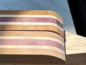
The next step was to trim each piece to be exactly 1 inch wide. The tricky part here was keeping the stripes centered. I took the easy way out and tried to just remove the same amount on each side and hope that the stripe would remain centered. In theory it should, but things happen…
One reason to make them extra wide and then trim them to width was that even though I cut the strips as accurately as I could, I wasn’t sure with what dimension the stack-up would end up being. Also, I wanted to make sure that the sides were perpendicular to the bottom/reference face. I needed to remove 1/8 inch on each side, but to be paranoid, I removed 1/16 from alternate sides. That is, I cut one side so that the total width was 1 3/16, then cut the other side for a width of 1 1/8, then the first side for a width of 1 1/16, and then the second side for a total width of exactly 1.
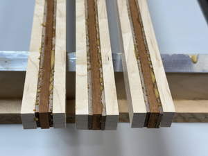
I don’t know why, but in some cases the stripe was centered at one end, but slightly off at the other end. This was where only needing 2˝ of the 3 boards came in useful. I could make the half that was off the half that I didn’t use. My boards now looked like:

|
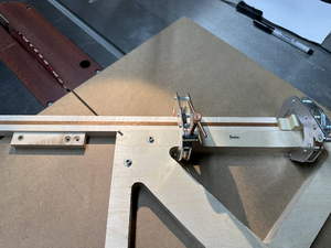
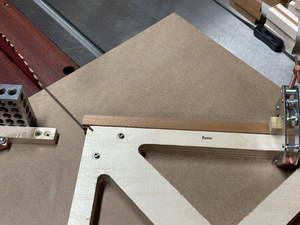
The next step was cutting the glued-up boards to the appropriate lengths and miters. For this, I made two simple jigs. One was a small cross-cut jig, and the other was a classic 45-degree jig.
The former was just a ľ inch MDF base with a fence positioned as accurately as I could 90-degrees to the kerf. To make it, I just cut two pieces of MDF, then cut a ľ” slot in the bottom of one and glued in a runner that was a snug fit in my saw’s miter slot. I put that in the miter slot and trimmed the MDF to get one side of the kerf cut. I then used an accurate square to position the fence (which was twice as long as the width of the half piece of MDF) perpendicular to the kerf cut, and then attached it to the MDF. I butted the other piece of MDF against the first piece and attached it to the fence. Then when I ran it through the table saw again, I got the second side of the kerf cut. This also gave me a cut partway through the fence. This resulted in a zero-clearance sliding table, where the edges of the cut in the MDF and fence were accurate indicators for positioning parts to be cut.
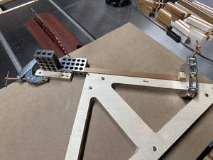
The miter jig was similar. I glued up a double thickness of plywood and cut it into a triangular shape. The key detail here is that the right angle had to be as accurate as I could make it. I then attached the triangle to an MDF base, also with a slider attached to the bottom. The theory of this is that even if the triangle is not set at a perfect 45-degree angle, if you cut miters using both sides, the error will cancel out, and the miters will close. In my case, I tried to orient the triangle as accurately as I could. I attached it with two screws, cut some test pieces *on the same side* of the triangle, assembled the miter joint, and checked it for squareness with an accurate square. I adjusted the triangle and repeated, until my two test pieces formed a good right angle. Then I attached the triangle to the base with more screws.

|
|
Each cross needed three 24-inch boards. I cut two of them in half, and only kept the best three of the four. This gave me three short pieces and one long piece, which would give me the three short arms and the long arm. I wanted to cut the pieces for each arm from same board and in order along the board, so that issues with the thickness not being consistent, or the center stripe not being perfectly centered would be minimized.
The cuts looked like this:
|
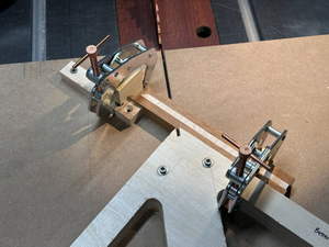
Initially, for the first few crosses, I tried to measure each cut very accurately, carefully align it on the appropriate cutting jig, and make the cut. This was very slow, tedious, and error prone. Eventually (for the last three crosses), I decided that a better way was to cut some reference pieces for a short arm. I cut them, fitted them, and adjusted them as appropriate. Then to make the cuts on the real boards, I would position the reference piece one the jig, clamp a stop block to the jig, and then position my real boards against the stop block.
|
This really sped up the process. Each of the three short arms are identical, and I was making three crosses at the same time, so I had 9 pieces I could cut with the same setup.
For the long arm, I positioned the reference piece as for the short arm, added a 6-inch spacer (I used two 1-2-3 blocks), and then positioned the stop block. This way, I only needed three reference pieces for the short arm.
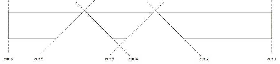
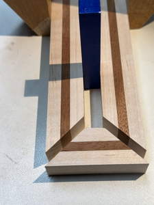
It was then time to cut the parts of each arm to final length. The arrangements of three pieces is shown below. It would have been more efficient in terms of wasted wood to invert the middle piece, but then if the stripe wasn’t centered, it would show more. Ideally, I would use the bottom edge in the figure as the reference against the fence, but as we’ll see, that wasn’t always possible.
|
|
Originally, I placed the bottom/reference face against the MDF bottom of the jig. I thought that having the blade go from the good face towards the back face would keep the wood from tearing out. However, I found that I tended to get some chip out on last corner of the miter cuts. Later, I tried putting the good face down, against the MDF. This worked better. The good face was well supported, so I didn’t get chip out there. Any chip out that I did get tended to be on the back inside corner of the miters, where is it almost impossible to see.
The order of the cuts is shown below
|
The first cut just squares one end.
|
Cut-2 cuts the first piece to length. I should note that for these cuts, I would position the piece to be cut against the fence, slide it until it was against the stop block, and then clamp it in place before making the cut. I probably could have, at least in some cases, just held the wood in place, but it didn’t take that long to do the clamping, and that avoided any possible shift during the cut.
|
The location of cut 3 is not critical. I just eyeballed it to remove as little of the wood as possible.
Cut 4 was the most critical one. This had to be spot on, as the small side had to exactly match the gap size. Furthermore, while it was fairly easy to adjust the sides of the “U” if they were slightly off, it was almost impossible to adjust the bottom of the “U” if it was off. To make matters worse, if we positioned it with the normal reference edge against the fence, we would be balancing it against a very short (half-inch) face, where it would be almost impossible to get it accurately oriented.
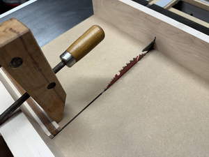
For this cut, I had to flip the piece 180-degrees and use the 2˝ inch side as the reference side against the fence. This alone should not be a problem, because the two sides should be parallel. However, this meant that my stop block would not be against the triangle of the jig, but floating somewhere off in space.
To deal with this, I screwed a small auxiliary fence in line with the triangle. This was not intended to align the piece to be cut as much as to provide a place to attach a stop block. I couldn’t just attach the stop block to the MDF directly, because then it would be in the way of other cuts. I had a gap between the auxiliary fence and the triangle, so that it wouldn’t get in the way of other cuts.
|
Unfortunately, I couldn’t use my reference piece to set the stop block on the auxiliary fence, so I had to adjust the stop block to give me the correct critical dimension. Then I marked where the stop block should go with pencil lines. Afterward, I just had to try to position the stop block to coincide with the lines. I would have preferred something more accurate, but this was the best I could think of.
As I’m writing this up, it just dawned on me that perhaps a better way would have been to position the stop block at the proper spot, then attach a second “stop block” against the first, on top of the auxiliary fence. Then, at least in theory, to replace the stop block, I would just have to slide it against the second block and clamp it in place.
Like cut-3, the location of cut-5 was not critical. Then cut-6 was made on the other jig.
|
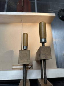
To align the pieces of each arm for the gluing, and to test the three pieces for size beforehand, I cut a rectangle of wood that had a good 90-degree corner, and which was 1˝ inches wide. This was used with two ˝-inch spacers. I was going to cut these out of wood, but then I remembered that I happened to have a commercial pair, so I just used those.
|
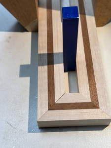
To use this, I would clamp my wood block against the longer side of the “U”, so that the end of the side was flush with the edge of the block. Then I would put the two spacers in, and align the shorter side agaist the spacers and against the 2˝-inch block. If everything was correct, the short end piece would fit against the miters on the two side piece and align perfectly.
In some cases, I would have to slide one side of the “U” a little to get the end piece to line up properly. This was a fairly easy fix, because then I could just trim off a little of the square end on the longer side, until the three pieces fit together correctly.
I made sure to label the three pieces on what would be the bottom face of the cross, so that they would stay together. I didn’t want to go through the trouble of cutting each arm from the same block of wood, only to get them jumbled and not know which piece should go with which piece.
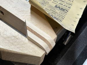
At this point, one could assemble the pieces into a cross, but it is much better to “bevel” the ends of the “U”, so that it appears that the pieces are woven together in a style similar to that of Celtic Crosses.
The first step was to roughly assemble each cross, and then mark the edges to be beveled. This isn’t strictly needed, but otherwise it is much too easy to accidentally cut the miter on the wrong side and ruin the piece.

|
The first step is to use the miter jib again to cut a 45-degree miter on the ends to reduce the thickness by about half. I didn’t measure this, I just eyeballed what looked good. I wanted the cuts to be as deep as possible, but to still leave enough of the ends to allow for gluing to the sides of the adjoining piece.
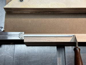
Initially, I just eyeballed what looked good and then made a pencil line on the MDF to indicate where to align the piece when I was cutting them. Later, when I was doing many pieces in batches, I found it easier to align a piece against the line, put a removable block against the end of the wood, and then clamp a stop block on the far side of the removable block.
|
|
|
Then, for each of the 4 different lengths, I could put the removable block in place, put the wood to be cut against it, place a stop block against the other end, remove the removable block, and then cut all the pieces of that length, making sure that my indicator lines were in the corner to be cut off.
|
This made sure that all of the cuts were identical, although this wasn’t strictly needed.
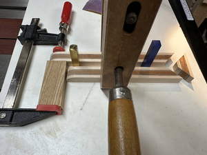
After this, I had all of the pieces cut, but I still needed to refine the bevels into a curve. In hindsight, I should have made a template and then used template-routing to cut them all, but I didn’t do that. I roughed out the curve on my spindle sander, just eyeballing what seemed to look good.
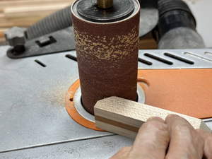
|
This resulted in something that looked like this:

|
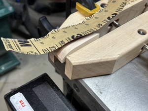
The next step was to smooth out the curve and remove any burn marks. I found the best, but the most tedious, way to do this was with hand sanding. I used a wooden clamp as a vice. I didn’t use backing for the sandpaper, because I wanted it to follow a smooth curve.
|
|
|
Later, I used some spacer blocks so that the piece I was sanding could rest on the table.
The following picture shows the difference between what it looked like when I finished with the spindle sander and what it looked like after the hand sanding.
|
The next step was to glue the three pieces of each arm into a single U-shaped piece. (Actually, for one of the crosses, I almost screwed up and started gluing the pieces together before I shaped the bevels, but fortunately I realized my mistake before doing any of the gluing.)
I took the same basic approach as was used in the video of using cyanoacrylate glue to avoid the need for clamps, but I used a slightly different process for doing the alignment during the actual glue up.
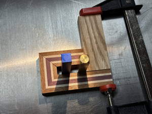
Just like in my test fit when I was cutting the pieces to length, I clamped my 1˝ inch block to the end of the longer piece, so that the faces were flush.
|
Then I put the two spacers in, aligned the other side piece, and clamped them together.
|
I always did a dry fit to make sure everything worked. To my surprise, in a few cases, it looked like the lengths of the sides of the U were slightly off. I couldn’t understand how this could be, as I checked them when I cut them, and as far as I know, they were good then. In any event, I had to do a small amount of emergency trimming just before gluing. This would change the curve at the bevel slightly, but not enough to be noticeable.
I found the gluing process somewhat stressful. I applied a drop of thickened cyanoacrylate to each face of the of side miters, sprayed some accelerator on the two faces of the end piece miters, got it aligned near the mating pieces, and then slid them together, aligned them, and held them together for a few seconds. I found it stressful as I only had a few seconds to get it aligned properly before the glue would harden. After the few seconds were up, I could remove the clamps and spacers and have a complete arm.
|
|
|
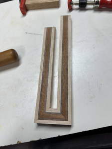
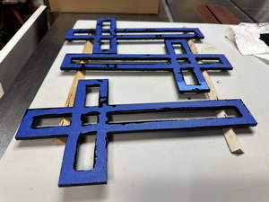
After gluing all of the arms together, I had something that looked like this.

|
The next step was to glue the four arms together into a full cross. The three short arms were identical, so how they were arranged didn’t really matter. The glue up was complicated enough (there were 8 surfaces to glue together) that I didn’t think I could do it with cyanoacrylate, so I opted for normal wood glue.
The first step was to do a dry fit and final check. Most of the time it worked fine, but again for unknown reasons, a few had some small gaps that needed adjusting.
For the actual gluing, I put some tiny dots of glue on the beveled ends and then carefully assembled the crosses. I wanted to avoid squeeze out (although I still got a little, which needed cleaning up). These joints don’t need to be totally strong—they just need to hold the cross together long enough to attach it to a backer board.
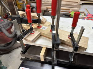
As this was wood glue, I needed to clamp the pieces together while the glue dried overnight. I used the arrangement shown below.
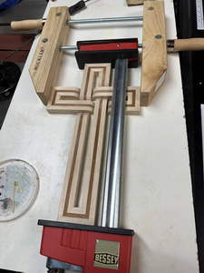
|
I needed to make sure that the pieces of the cross stayed flat on my laminate table. I wanted to tighten the clamps just barely enough to close any gaps, but I was acutely aware that the glue joints on the miters were not that strong, and that if I tightened these clamps too much, I could easily break one or more of the miter joints.
After the glue dried overnight, I removed the clamps and I had essentially a complete cross. However, the joints were rather fragile, and it would be very easy to break it. To add stability, the cross would be glued to a plywood backer. The glue joint from the cross to the backer provided the bulk of the stability.
The backer was in the shape of the cross, but slightly narrower, so that when the cross was hung on a wall, it would sort of seem to be floating a quarter inch away from the wall. The video didn’t give dimensions for the backer. I thought that making an 1/8 inch overhang would be too little. Making the overhang 1/4 inch would leave the plywood only 1/2 inch wide, which I thought was too narrow. So I made the overhang 3/16 inch, which made the plywood pieces 5/8 inches wide.
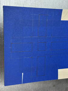
I first cut out rectangles of 1/4 inch plywood to the total width and length that were needed. This defined the ends of the plywood crosses. I then laid out the other cuts that I would need.
|
|
My scroll saw skills are somewhat rudimentary. I found that I could cut the outside cuts quicker, more easily, and more accurately on the table saw. I first made the cuts going in the sides.
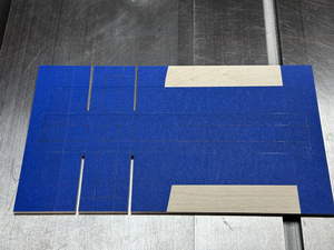
|
Then I made two opposed cuts going the long way.
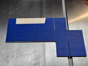
|
Then I made the other two long-way cuts.
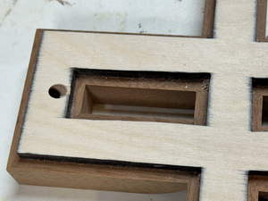
Because the table saw blade isn’t vertical, this left some funny corners. These were easily cleaned up with a little chisel work.
|
|
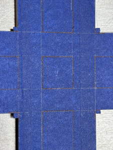
After that, it was time for the scroll saw. I had to cut out all 5 internal spaces on each cross. This took me a while, but when I finished, the crosses looked like:

|
The inside edges were not nearly as clean and accurate as the outside edges, but the inside edges are almost impossible to see unless you look at the back of the cross.
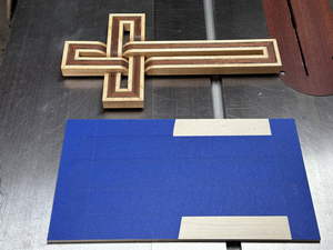
The next step is paint/stain the edges black. Originally, I tried black spray paint, but that didn’t work too well. I found that a black opaque stain worked better. The point of the tape is to keep the black off of the faces of the plywood. It just makes for a neater result.
|
You can see the reason for the tape. Despite my efforts, more stain got on the faces than I would have liked.
After the paint/stain had dried, and the tape removed, I did a light sanding to get rid of any black that had spread under the tape. Then I glued the plywood to the cross. To do this, I put the cross upside down on my laminate board and ran a thin bead of glue along the centerlines. I tried to use little enough to get very little squeeze out, but I always seemed to have more squeeze out than I would have liked.
I put the plywood over the cross and centered it by eye, trying to get the reveal even on all of the sides. Then I carefully clamped some blocks over the plywood to get a good bond
|
After this had set for 30-60 minutes, I removed the clamp and cleaned up the squeeze out.
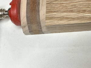
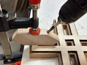
In the original video, she didn’t go into any details as to how one might hang it on a wall. I decided that the best way would be to drill an angled hole in the middle of the top. Then you could mount the cross on a wall by just partially nailing into the wall a small brad. On the other hand, if the cross was laying on a surface, it would still lay flat.
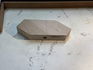
To do this, I created a small jig.

|
I didn’t want to try to drill an angled hole, so I drilled a hole perpendicular to the edges of a piece of scrap, and then cut the sides at the desired angle. This resulted in the exit hole being more or less centered in the middle of the block.
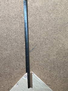
|
I marked where the edge of the hole ended up. I clamped it on the cross in the proper spot. This also prevented the edge of the hole being torn up. I marked the depth to cut with a piece of tape. I carefully drilled a hole up to the edge of the tape, all the while being paranoid that I screwed up and would pop out on the good side of the cross and ruin it. (Fortunately, that didn’t happen).
|
This resulted in a fairly neat hole.
|
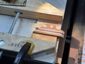
After this, there was final sanding and some “phudging”. Some of the miter joints were not as neat as they could have been. To “fix” this, I followed the advice of the video. I put a small amount of glue over the joint, sort of pushed it into the gaps with my finger, and then while it was wet, I sanded it with my random-orbit sander. In theory, one should get the sawdust mixing with the glue in the gap, but I’m not sure how well that works when there are different colors of wood next to each other. My goal was to get the glue off of the surface (so it wouldn’t interfere with the finish, but have some remaining in the gap).
|
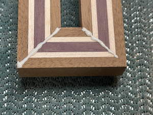
|

|
This isn’t perfect, but it was better than having a gap.
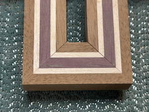
At this point, the crosses looked like:
|
I put some Watco Danish Oil on it, and the colors popped.
|
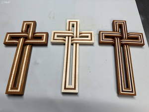
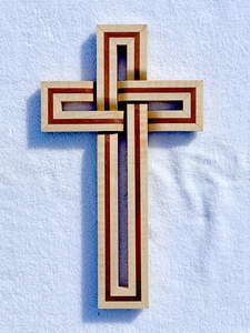
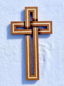
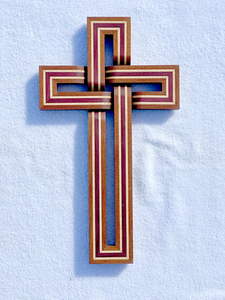
Here are the final results:
|
|
|
|
I like the simplicity of the single stripe, but I think I prefer the double stripes better. I can’t decide which of those I like better, however. There is something to be said for the one with the maple on the outside, but there isn’t that much contrast between the other two colors. The one with the maple between the other two colors has more contrast, but I’m not sure I like the darker outside as much as the lighter.
This is what they look like hung on the wall.
|
|

|
|
|
|